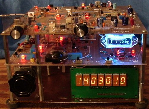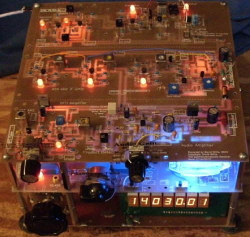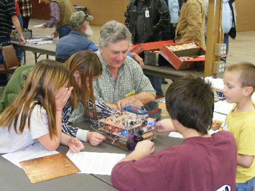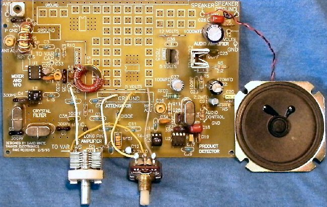


The Electroluminescent ReceiverShown with the parts included in the kit with the optional LED Frequency Counter, Frequency Stabilizer (mounted in the bottom back) and S-Meter. Covers the CW portion of 40, 30, 20 and 17 Meters. Can be easily modified to cover the SSB section of 40, 20 and 17 Meters. Easy to follow pictorial instructions makes it a fun build. Designed as a blood thirsty DX machine, it appeals to the young and the young at heart. With large boards and plenty of room, it is easy to insert parts, diagnosis, and make modifications. The LEDs show circuit function - MOSFET (13 used) circuit health, gain of the amplifiers, oscillator drive, mixer gain, switching functons, and 12V power - it is the easiest superhet receiver to diagnosis and repair ever! The ELR, which runs with the big boys, is finding a nitch with the little ones...and the YL's, too! Please note this reference, "Rediscovering the Band-Imaging Receiver", by David Newkirk, W9BRD that talks all about band imaging receivers and list all that have been published.  For details click Elk City Hamfest, OK 2011 .
To see past front cover pictures, go to "Front Cover Pictures".
|
|
LED diagnosis, large circuit boards, wide traces/pads, and step-by-step pictures make this the easiest double conversion receiver you will ever put together. For more information read Amateur Radio ReceiverAn CW/SSB receiver that covers the first 100-150 kHz of the 40 and 20 meter bands and all of the 30 and 17 meter bands. Bandwidths can be modified. SWL ListenersThe tuning range of the VFO is expanded to 500kHz to cover most of the 41/31/19/16 Meter SWL bands. Duncan Watson and Gary Rondeau have sent in modifications they made for improved performance of their receivers. They include VFO, crystal filter, AM Detection, and AGC modifications and improvements - check them out. LED Frequency Counter!Check out Circuit Details and |


Home page has several great links to LED sites.
These pages contain the history of the MOSFET
receiver, going back into the 70's.

Includes:
Learn how to solder from the "How to" sites listed.
Ugly construction/Manhattan construction sites.
Toroid information.
The best QRP sites.
Receiver Projects and Receiver Information.
If you are caught in a frame or on the
CD-ROM and want to check on updates,
click on one of the following sites:
http://www.amateurradioreceivers.net
http://www.qsl.net/wn5y

