
|
The new ELR Rev 2 boards currently being sent with the receiver kits have the parts for integrating the stabilizer with the VFO on Board 1. Two cables connect to the receiver. First, a cable between the stabilizer and the varicaps in the VFO. Second, a cable between the "Stabilizer" box between the two VFO amplifiers and the "VFO IN" at the upper left of the stabilizer board.  VFO CoilThe VFO coil is wound with 19 turns when using the stabilizer. If you wind it with 18 turns, just pull the windings together to get the 14 MHz VFO within range of the 8pf ceramic trimmer. The varicap on the 8pf trimmer raises the 14 MHz frequency 300-400 kHz, so the VFO coil is wound with 19 turns, instead of 18 turns without the stabilizer. Readjustment of the toroid windings will be necessary to get the 8pf trimmer in the 14 MHz range of the VFO. The addition of the varicap will raise the 14 MHz frequency and bringing the windings closer together will be necessary. |
|
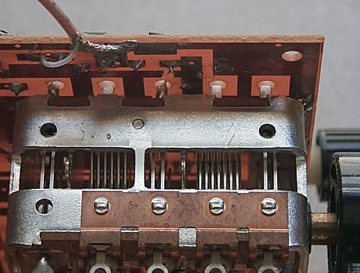
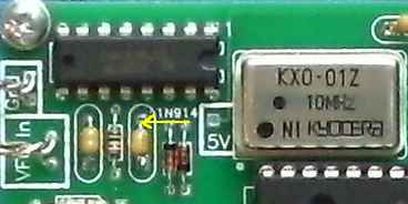
There are two connections to Board 1 in the VFO section, a third one to the reset button and a fourth one to 12 volts and ground. A box labeled "Stabilizer" between the VFO Amplifiers on the edge of Board 1 of the receiver PCB goes to the "VFO IN" connection on the Stabilizer board. At the VFO, above the main tuning capacitor, there is a box labeled "Stabilizer In" that goes to the box labeled "Varicaps" on the Stabilizer board. A reset button, mounted on the front panel, is connected to the "Reset" box on the stabilizer board. Power (12 volts) is connected to the power connection of the receiver (or wherever is convenient), and ground to a ground plane connection. VFO Connections Inside the "VFO IN" box are the connections to the VFO "Stabilizer" connection on the receiver board. The lower one is the VFO connection (connected to the .01 input capacitor) and the upper one is the "Gnd" (ground) connection. It is easier to make this connection first, mount the stabilizer board, then make the connection to the VFO "Stabilizer" box on Board 1. ____Solder the shield of a 6" length of miniature coax cable to the ground plane underneath the board. ____Solder the center conductor to the trace connecting to the .01 cable underneath the board. You might be able to get the center conductor through the hole on the top side but it is much easier to solder to the trace underneath. 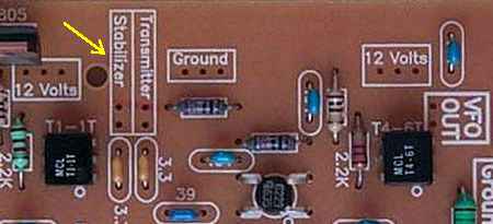 The yellow arrow points to the connection between the VFO amplifiers that connects to the cable from the "VFO IN" connection on the Stabilizer board. Miniature coax is used for the connection. If desired, wire loops can be installed at both the "Stabilizer" box and in the "Ground" box for easy connection points. |
|
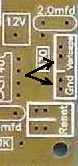
The output of the stabilizer is marked "Varicaps" and "Gnd". ____Connect the cable to the stabilizer first. Next mount the stabilizer board, then connect the cable to the receiver board as shown below. Use about a 5" length of the miniature 75 ohm coax. Note the ground and center wire connections. There is a "Gnd" label next to the Ground hole. Or solder the shield underneath the board on the ground plane. |
|
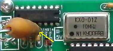
The picture above shows the connection of the output of the stabilizer to Board 1. The connection is made underneath the board. The shield is soldered to the ground plane and the center conductor is soldered to the pad underneath the board where the "Stabilizer In" hole is located. See the picture below. 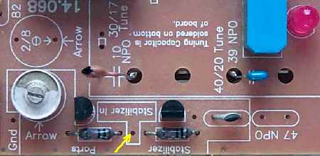 This picture shows the connection on the top side of the board. Note the yellow arrow pointing to the connection hole. This hole and both resistors connect to the same pad underneath the board. Please note that connecting the stabilizer to the VFO will change the frequency of the VFO. To set the 14.000 (or 14.068) MHz base frequency of the VFO, compress (too high frequency) or expand (too low frequency) the turns of the VFO coil. If spreading (expanding) the windings on the VFO does not get the VFO to 14.000MHz, take one winding off the VFO coil. When adding the stabilizer, you are adding some capacitance to the VFO tank, so the most likely adjustment will be raising the VFO frequency from 13.xxxMHz back up to 14.000MHz. Connecting the "Reset" Connection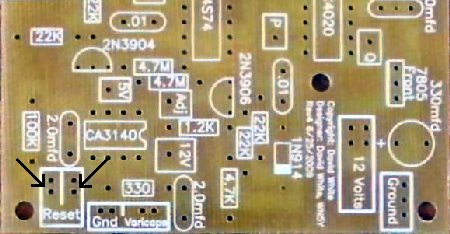 ____Mount and connect the "Reset" Push Button to the stabilizer. The Reset button is a small push-button switch, closes on push. Be sure to use enough wire length to reach where the Reset button will be mounted on the front of the receiver. Twist the wires together to keep them neat. Connecting 12 Volts and Ground ____Connect the 12 Volts and Ground to the stabilizer board. Even though pictures of the receiver show the 75 miniature coax connecting to 12 Volts, regular hook-up can be used. Two pieces of wire twisted together work great. There are enough holes here to install wire loops for connection points for the 12 volt and ground connections if desired. The 12 volt power supply to the stabilizer should be filtered from the receiver. Make a connection to the receiver only at the BOLD 12 Volt connections, where the RF Chokes are located. Using an additional RF Choke at the 12 Volt connection to the Stabilizer PCB wouldn't hurt. ____Board 1 and the Stabilizer Board should be mounted in their running positions, then secure the connection between the stabilizer and the PCB board so that it doesn't flop around and cause frequency changes since it is close to the main tuning capacitor. |
|
Have the stabilizer turn on at the same time as the receiver. The VFO will do some short term quick drifting, as the 2N5486 warms up from the operating current. The stabilizer should lock very fast. The current integration of the stabilizer with the VFO has provided excellent stabilization. The stabilizer should be reset by pushing the reset button after about five minutes. Depending on how fast the room temperature is changing, normal reset times are about two to four hours. There will be a slight, short term drift when changing VFO frequencies as you change bands. |
|
If the stabilizer does not lock up after 30 seconds or so of operation, then some troubleshooting is in order. There can be some small movement of frequency due to the initial heating of the 2N5486 changing the frequency a few kilohertz for the first minute or so. Some Basics Checks1. A simple check of the 74HC4020's can be done with a DVM. All the outputs are square waves and a dc voltmeter will show approximately 2.5 volts at Pins 1 and 2 (Q2 and Q3 connections). If the chip is not receiving the VFO signal (Pin 10) or is dead, the output will be either 5 or 0 volts. Check the second 74HC4020 (middle top of board) at Pin 4 and 7 for over 2 volts. Zero or 5 volts indicates no signal input at Pin 10 (Q connection) or a dead part. If you are having problems with the above tests, scroll down to checking the ICs with a frequency counter. These tests will walk you through all the frequencies the ICs should be seeing. 2. Disconnect the 4.7 Meg resistors from the 2N3904 and 2N3906 where they connect to the collectors. Solder a 10 meg resistor (value is not critical, smaller/larger values will decrease/increase timed voltage changes) to the hole in the Adj box next to the 4.7 meg resistors. 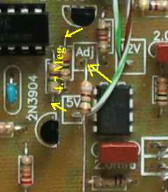 Connect power and check for 5 volts at Pin 6 of the CA3140 - leave the test lead connected. Short the Reset connections and the voltage should be very close to 5 volts. Ground the loose end of the 10 meg resistor and the voltage should increase slowly at a rate of 1 volt every 2 to 4.5 seconds. When the Adj is removed from ground, the output should remain stable. Connecting the 10 meg resistor to 12 volts should decrease the output voltage at Pin 6 at a slightly faster rate. If you are having problems with the above tests, check that Pin 2 of the CA3140 has 5 volts. A bad solder joint or forgetting the jumper between the 5V box next to the CA3140 and the 5V box at the top of the board (between a .01 and 10mfd caps) will result with no voltage at Pin 2. If the tests checked OK above, remove the 10 meg resistor. 3. The frequency discriminator can be tested by reconnecting the 4.7 meg resistor to the 2N3906. Connect the VFO (any frequency) to the Stabilizer ("VFO In" box). The output voltage (Varicaps box) should decrease at a rate of 1 volt every 100 seconds (within 20-30%). Connecting the 4.7 meg resistor to the 2N3904 (remove the 4.7 meg resistor to the 2N3906) should increase the voltage the same amount and time. The VFO frequency should be stable with both resistors in place. With both 4.7 meg resistors connected, if the voltage goes above 9 volts and stays there even when the Reset button is pushed, check the leads on the 2N3906. If OK, replace the 2N3906. Check the transistor if you have an Hfe test on your DVM. If the voltage goes to zero volts and stays there even when the Reset button is pushed, check the leads on the 2N3904. If OK, replace the 2N3904. Check the transistor if you have an Hfe test on your DVM. All the readings below are with the VFO at 14 MHz. Make frequency checks at the top of the chip - this will double check for bad solder joints. When using the LED frequency counter, take the readings with a jumper connected to the top of the second .01 cap away from the VFO input. This location will read all the frequencies from the chips. See pictures below: |
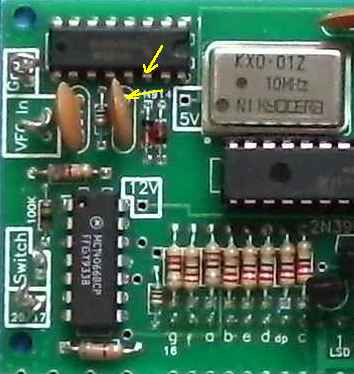 Shows location with kits that used large caps and Pin 14 input to the 74HC4046. |
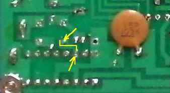  Upper pic shows the trace to connect underneath the board. Lower pic shows a connection wire tacked soldered to the input for measuring digital frequencies at the stabilizer ICs. |
 Shows the location where a clip lead can be attached with kits using the small caps. |
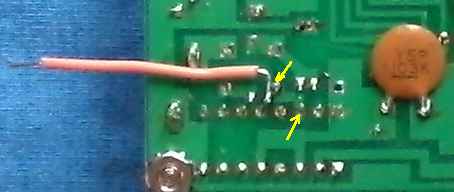
 Shows clip lead attached for measuring digital frequencies at the stabilizer ICs. |
|
Go back to the regular "VFO In" location for reading frequencies from the receiver after the following tests. ____Connect the VFO, reading around 14 MHz, to the "VFO In" box. ____Use a frequency counter and check for a reading at Pin 10 of the first 74HC4020 (above the 32 MHz Oscillator). It should read 14.xxx.xx MHz. If no frequency here and the LED is on, check for bad solder joints around the T1-1T and interconnecting .01 capacitors.____Check for a reading at Pin 1 of the 74HC4020, it should be 3434 Hertz (3.43 kHz). ____Check for a reading at the "P" jumper on the board, it should be 215 Hertz (0.22 kHz). ____Check for a reading at pin 4 of the 74HC4020 at the top middle of the board, it should be 53 Hertz (0.06 kHz). ____Check Oscillator output. Check at Pin 2 of the 74F74 (74S74) for 32 MHz. The oscillator output may read a little above or below 32 MHz. The actual frequency doesn't make any difference on the operation of the stabilizer - stability is the only thing that counts from this oscillator.  Arrows indicate the places to check for a frequency, the readings will vary depending on band, etc, but you are looking for a missing frequency. At a 14 MHz VFO frequency the top .01 will show 218 Hz (0.22 kHz) and the bottom one connected to Pin 5 of the 74F(S)74 can vary between 10 to 100 Hz (0.01 to 0.10 kHz). The other side of the .01 caps will not show a meaningful reading. If no signal is indicated at one of the .01 caps: First, check the 22K resistors for correct value and correct polarity of the diodes.Second, check the ICs (74HC4020 and 74F74) for unsoldered active pins and power pins - ground (Pin 7 or 8) and +5 volts (Pin 14 or 16). (Not all pins are used on the ICs). Sudden driftingSudden drifting, with no jumping, is a bad solder connection at a ground or 12 Volt pin at an IC or a low value integrator resistor (the 4.7 Megohm resistors). Check the connections to the transistors also. Jumping of the frequency, around the stabilized frequency, can be a bad ground at one end of the miniature coax. A lot of movement during setup of the boards can cause the ground lead to break right at the cable where the tinned ground shielding ends against the insulation. Pull gently at the cable to make sure there is a strong connection.  Arrows show location of integrator resistors - 4.7 Megohm
If the output of the stabilizer (relay output or "Varicaps" box) immediately goes to 10 volts or zero volts at turn on, check the 4.7 Megohm integrator resistors. Also, check the transistors as noted in Step 3 above. You can double check this by taking the input frequency (the VFO) off the stabilizer input and reset the stabilizer. The output voltage should be around 5 to 6 volts, then touch the VFO output to the input of the MOSFET amp, the output will jump to 0 or 10 volts immediately. One of the 4.7 Megohm resistors is not 4.7 Megohm, instead, a very low value. It is very difficult to blow a CMOS chip, unless you put the 5 Volt regulator or IC in backwards. Otherwise, your problem has to be a bad solder connection on the board. An unsoldered pin at one of the ICs is the most likely problem to occur. Check carefully! Resistor/Capacitor MistakesIf both the 4.7 Megohm resistors are too low in value at the integrator, there will be modulation in the output of the VFO. This modulation will be heard in the speaker. Remove the wire to the "Varicaps" box on the Stabilizer, connect the wire to a ground on Board 1 to test if it is definitely coming from the stabilizer. If the varicaps are installed on Board 1 and not connected to ground or 5 Volts (on the output side of the VFO 7805 regulator), the VFO will pick up 60 cycle hum and the VFO will be very unstable. When testing the VFO without the stabilizer, ground the varicap input voltage connection (Stabilizer In - between the two 100K resistors). Check the integrator resistors - two 4.7 meg. There is one 4.7k resistor in the kit that could have been accidentally placed here. Check the soldering on the 2.2mfd red square integrator capacitors around the CA3140. The leads on these capacitors are very thick and solder will flow on the board first before wicking onto the leads of the capacitor leaving a small gap around the leads. Check with a magnifying glass. There was one case where everything checked out but the stabilzer would not work. One of the .01 caps from the ICs to the integrator was lifted from the board and measured. It only measured 10pf - a bad .01 cap. After it was replaced with a good .01 cap, the stabilizer worked. A rare case, but it can happen. This problem should show up when testing the frequency discriminator. |
Send E-Mail || Amateur Radio Receivers || Electroluminescent Receiver || Back to Basic Instructions || Back to Frequency Stabilizer
