

Finast 5mg $141.86 - $2.36 Per pill
| Humboldt | Finast Chillicothe | Valhalla | Finast Remsen |
| Kimberley | Murray Bridge | Mandurah | Vancouver |
| Trossingen | Taucha | Schleiz | Ribnitz-Damgarten |
|
This counter was first known as the Modular Dial developed by Bill Carver, W7AAZ, and published in the Spring 1998 issue of Communications Quarterly. When I took a serious look at the Modular Dial in 2006 it seemed a good match for the Electroluminescent Receiver Kit (ELR). I was looking for a counter with an LED display and flexible add/subtract offset frequency functions. When I contacted Bill, W7AAZ, he handed over the project and told me to run with it. There was a lot of work to do. The original PIC16C62 chip had become obsolete and the code needed some rewriting to work with the modern updated PIC16F72. There had been a lot of updating on the way code was written since the original PIC chip. A lot of help, study, and rewriting was needed to get it working. Luckily, there was a PIC programmer who worked across the street from my work place, a huge surprise, since I never expected to find anyone who had even heard of PICs in my little town of Pampa, Tx. He had been a programmer for over 10 years and understood Bill's code. We met at lunch, working on paper napkins, until we got it working. I also had the help of another dyed-in-the-wool homebrewer who had considerable PCB design work under his belt. His suggestions on layout and some circuit design was invaluable. He followed along with the design of the PCB helping with final decisions on the layout. The original board was redesigned with most of the interface circuits integrated on the PCB so it would be easy for ELR and general purpose use in other receivers/projects as well. The goal of the new design was to make it as universally usable as possible with the option of using any LED display of the builder's choice. |


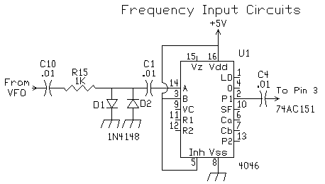
The Frequency InputsThe counter has two signal inputs, the black squares labeled "VFO IN" (left side) and "OSC IN" (right side). The "OSC IN" is counted once when first turned on for two seconds, briefly displayed as a diagnostic tool and saved. "VFO IN" is counted 5 times a second, either adding or subtracting the "OSC IN" value and displaying the result to the nearest 10 Hz on seven LEDs.
 Both frequency input circuits are identical using a 74HC4046. The input circuit comes from AADE. Neil uses this circuit on all his frequency counters. It does very well at low drive levels (input range 50 mv to 5V p-p) which makes it very easy to work with any VFO/oscillator circuit. Connecting this counter to the VFO in the ELR does not make any noticeable difference in the output. For ideas interfacing to other projects, check out Neil's Applications Page. The 74HC4046 can be overloaded causing improper counting and, in some cases, shuts down counting altogether. If any problems occur when interfacing the counter to a VFO, lower the drive level with a lower value input capacitor. |
 |
 |
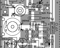
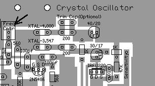
| VFO to counter | Xtal Osc to counter |