


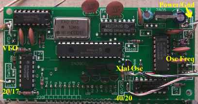
 All the board connections labeled in yellow.
Small coax is used for the VFO and Osc Freq connections. Other connections are single wires. The pictures for this section come from the first PCB version of the counter, but no changes were made in the second PCB that change what is said here. Crystal Oscillator Connections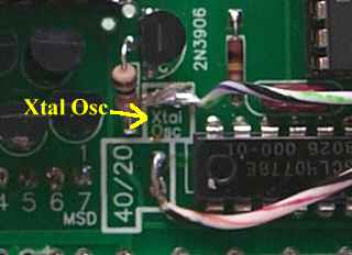 "Xtal Osc" connection shown on the Frequency Counter board.
 The wire from the 'Xtal Osc' square is connected to the 'Freq Cntr Xtal Osc' box at the Crystal Oscilltor on Board 2 as shown above. There is a wire loop installed in the box where the wire is connected. It can be connected below the board if desired. Oscillator Frequency Connection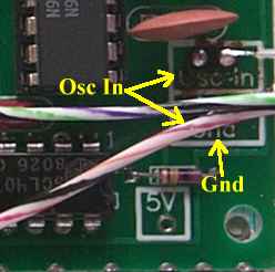 The Oscillator Frequency connection on the Frequency Counter PCB. 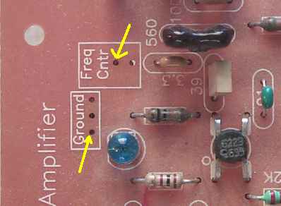 This picture shows the location of the connection for the "Osc In" and "Gnd" from the Frequency Counter. Connections can be made from the top or bottom as you please. Putting a wire loop in the 'Freq Cntr' and 'Ground' box make it easy to connect the coax. 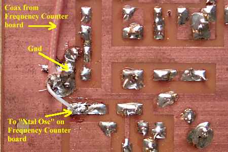 The connection shown made on the bottom of the board. It is a lot easier to make the connections to the ground plane and "Freq Cntr" on the bottom side of the board. |
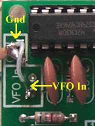 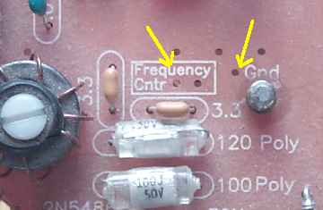 The place on Board 1 at the VFO for the "VFO In" and "Gnd" connections from the frequency counter board. 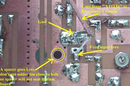 The picture above shows how the connections are made underneath the board. Be careful to leave enough room around the hole for the spacer to seat against the PCB. |

|
The frequency counter will switch automatically as you switch the Bandpass Filter and Crystal Filter switches. You will notice a slight delay (about 1-2 seconds) and see the frequency counter read the offset frequency. Then one second later will show the correct frequency for the band you have selected. When powering up the receiver, depending on the band the receiver is on, there may or may not be a delay on the crystal oscillator frequency. When turning the receiver on, off and then back on, wait five seconds or so for the delay capacitor at the crystal oscillator to fully decay. If you get the wrong frequency at start up, just switch to another band (wait for it to show the new band) and back, the frequency counter will correct itself. |

|
The installation of a rotary switch uses different connections than using the slide switches on Board 1. Skip the instructions "The 20/17 and 40/20 Connections" and go to Connecting 12 Volt Power after wiring the rotary switch. "The 20/17 and 40/20 Connections" instructions are for wiring the slide switches on Board 1. 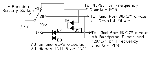 Depending on where you mount the Rotary Switch, you may want to make your connections to Board 1 on the copper traces underneath the board for a cleaner look. Top connection coming from "40" switch contact: 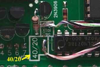 To "40/20" on Frequency Counter PCB.
The middle connection from the "30" switch contact (on Board 1, Section 3): 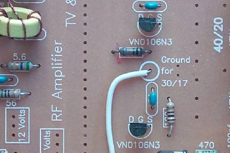 To Gnd for "30/17" circle at Crystal Filter
The two locations for the bottom connection: 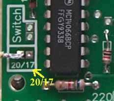 "20/17" on Frequency Counter PCB
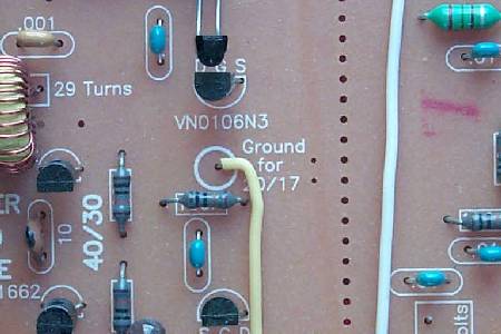 Gnd for "20/17" circle at Bandpass Filter
|
Send E-Mail || Amateur Radio Receivers || Electroluminescent Receiver || Back to Ham Radio Instructions
Back to LED Frequency Circuit Details || Back to LED Frequency Counter Construction
