

|
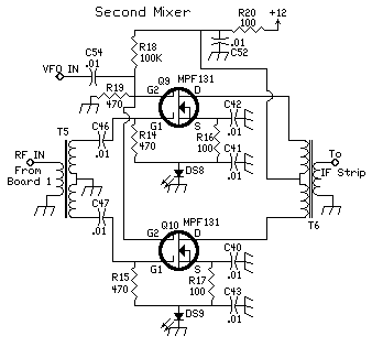
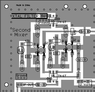
The second mixer is a tamed down version of the first mixer. Sensitivity is not an issue with this mixer, since it is fed a strong signal from the crystal filter. The resistors on the G1 terminal of the MOSFETs, changed to 470 ohm, help to raise the dynamic range of this mixer, as well as tame down the sensitivity. This makes for a very stable mixer. By using only .05 volt bias on the G2 terminal of the MOSFET, the brightness of the LEDs is a direct reflection of the drive the mixer is receiving from the Crystal Oscillator and Amplifier. Diagnosis is simple. If the LEDs are off when the receiver is fired up, the mixer is not receiving any signal from the Oscillator/Amplifier chain. When the crystal oscillator is switched from 4.000MHz to 3.547MHz, or vice-versa, the LEDs will flash, showing the transition between the two frequencies, as the oscillator turns off momentarily switching between the frequencies. Ninety percent of the birdies of the receiver are a result of the VFO frequency getting into this mixer, and mixing with the signals the mixer picks up from local strong broadcast/TV stations or stray receiver signals. This is the reason for the set of soldering pads around the mixer. The pads are used to place a shield around the mixer. This also helps considerably in keeping the VFO signal out of the mixer. When using very good outdoor antennas, shielding the second mixer is very important. Shields only 1/2" to 1" high do the job very well. Wires can be looped through the holes, soldering them on the bottom ground plane, then to the shields on top of the PCB. In a very early prototype in which signal pickup was a major problem, these shields cured the problem. For the perfectionist, however, putting a top on the shields, and doing the same thing underneath the board will completely isolate this mixer. The tendency of this mixer to pick up local broadcast/TV/FM signals was clearly shown when taking the receiver from town to town and getting birdies at different frequencies in the receiver. The builders that like to see all the LEDs, and don't install much shielding, will notice this effect. A lot of the birdies are masked underneath band noise when the receiver is peaked to listen on a ham band, so this is not problem in most situations. The output of this mixer was designed to be strong enough to mask the IF strip electron shot noise, so that when a band is tuned in, the noise of the band should raise the S-Meter reading slightly. |
|
|
|
|
Send E-Mail || Amateur Radio Receivers || Electroluminescent Receiver
