

|
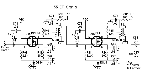
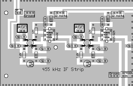
Since the LEDs are in the drain circuit of the MOSFETs, variation of drain current will show up in the brightness of the LEDs. These LEDs could actually substitute for an S-Meter, as the intensity of their flashing will be in direct correlation to the signal level of the station being tuned. In a very early prototype, one of the LEDs was brought to the front panel with the S-Meter, where it would flash along with the action of the S-Meter. This is one of the reasons why Board 2 is placed on the top of the completed receiver, so the action of the LEDs can be seen. The flashing of the LEDs in rhythm with the incoming signal is one of the fun aspects of this receiver. If you really like this action, the third amplifier (AGC Amplifier) can be connected to the AGC line, and have three LEDs flashing all at the same time. AGC action is diminished somewhat, and the receiver volume will have to adjusted for very loud signals. Doing this for receivers used with transmitters is not recommended, the volume of the speaker will blow you away. But for the SWL listener, it might be a cool addition to the receiver. To make the modification, take off the 100K resistors of G2 on the MOSFET at the AGC amplifier and tie the AGC line directly to G2. Leave the .01 bypass cap in place. This is a very low noise 455KHz IF strip. I have replaced all my IF CA3028 designs with this one, as I believe there is just no comparison between the MOSFETs and an IC circuit design. This circuit is readily adaptable for use with high end 455kHz IF filters, for the resistor on G1 sets the input impedance for the amplifier, which makes matching a crystal filter to the amplifier very easy. This circuit is basically an adaptation of the IF strip from the Progressive Communications Receiver, in most of the 1980's ARRL Handbooks. References |
|
|
|
|
Send E-Mail || Amateur Radio Receivers || Electoluminescent Receiver
