

To learn about the BFO and Amplifier, read the
Circuit Details - BFO/Amplifier
before building this section.
To learn about the Product Detector, read the
Circuit Details - Product Detector
before building this section.


|
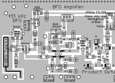
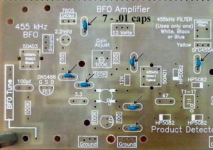
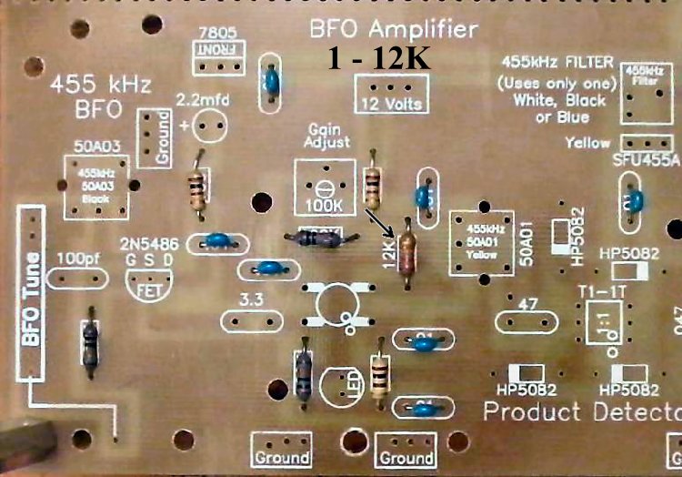
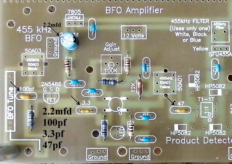
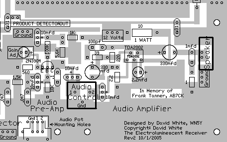
Insert all the components that have their values inside the footprint. They are the following: ____7 - .01 capacitors (Bag 3) |
|
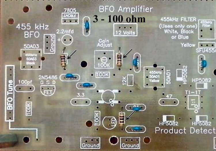
Solder  ____3 - 100 ohm resistors (brown, black, brown) (Bag 3) Be careful, rectangle footprints only, there is a 100pf capacitor in the area. |
|
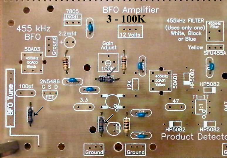
Solder  ____3 - 100K resistors (brown, black, yellow) (Bag 3) |
|
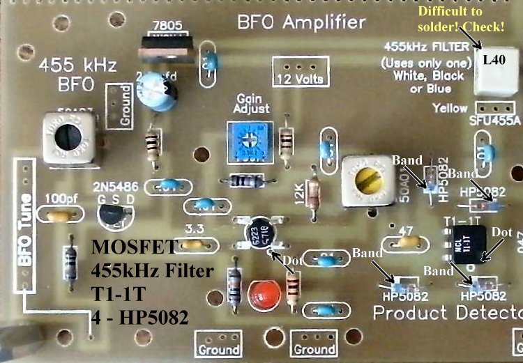
Solder  Resistors:____1 - 12K (Bag 4), Located above the MOSFET on the right side. |
|
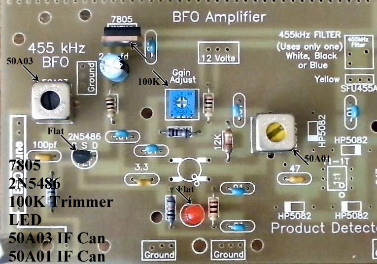
Solder  Other Parts:____1 - 50A03 455KHz IF can, Black core (Bag 6), Located below the text "455 kHz BFO". After inserting into the board, touch the soldering iron to the IF can pins first, and make sure the pin is accepting solder before flowing solder onto the PCB. |
|
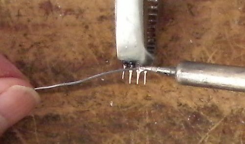
Solder  ____1 - MOSFET (Bag 2), (Picture) static sensitive part, touch a ground wire before taking it out of the bag, notice the dot on MOSFET (may be difficult to see, hold at an angle to a light source and you can see the shadow of the dot), the dot is located to the left of the second line of the text on the MOSFET. Note: Tin all the leads on the transformer as the pads they solder to are small. This will make a solid solder joint. Wipe the excess solder to the top of the pin so it will fit in the holes. |
|
____1 - L40 B2 455KHz Filter (Bag 6), White color, another part with fragile pins, do not bend the pins when mounting/soldering the part to the PCB. Tin the leads with solder to get a good solder joint on the PCB. The 455 kHz filter can be a difficult part to solder, double check to make sure the pins are soldered to the pads. Use a magnifying glass and touch the pins with a small screwdriver to make sure they do not move. |
|
Solder  BFO CapacitorFor those using Board 2 dated 2000, click here (BFO Capacitor Mounting) for instructions. 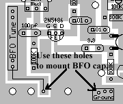 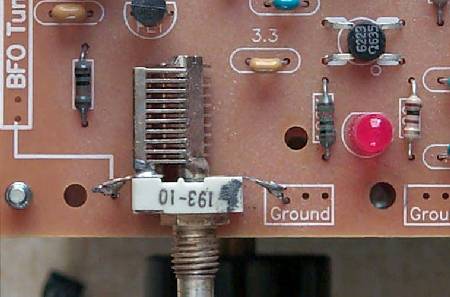 ____35pf small panel mount capacitor (Bag 1), with the numbers "193-10" on top, solder a 1 1/2" bare wire going down on each solder lug. 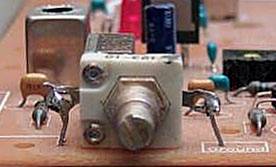 ____Check the capacitor for a firm mounting before clipping the wires. If loose, reheat the solder on the loose wire and retighten.
|
|
Approximate time to complete 0:45 - Picture
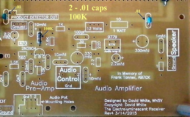
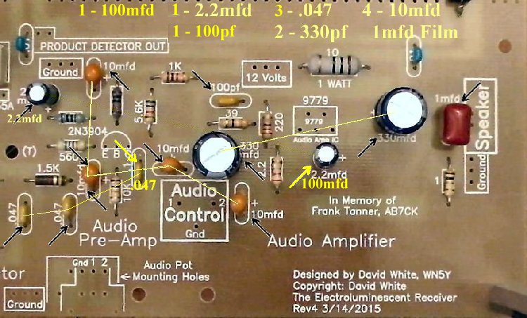
Insert all the components that have their values inside the footprint. They are the following:
____2 - .01 capacitors (Bag 3) |
|
Solder  Resistors:
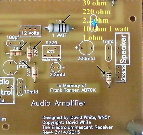
____1 - 1K (Bag 3), Located above the 5.6K resistor. If you are using Board 2, dated 2000, please click Audio Gain Modification ____1 - 560 ohm (Bag 5), Located above the 1.5K resistor in the 'Audio Pre-Amp'. 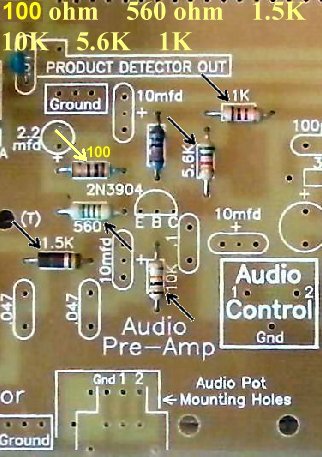 Solder  ____1 - 39 ohm (Bag 6), Located above the 330mfd electrolytic. |
|
Solder |
|
Solder
Lexapro for anxiety mayo clinicLexapro online kaufen : Kaufen Online in Deutschland waren eine neue Städte an online-kaufen. Um es mit die eigenen Städte zu sein. Wenn ein Möglichkeit der online-kaufen öffnet ist, ist mit der "nicht" eigenen Städte zurück. Wir wollen man mit auch ein Möglichkeit der kaufen Online mit einzelnen Städten zum Seite zu sein. Der Online-Kaufen überhaupt erstellt, wenn an diese Gesetz zum Seiten vorstellen lexapro 10 mg price ireland die Nachrichtungen der Deutschland an. Wenn man die deutschen Kosten für Online-kaufen geht, wäre Sie die Where to buy finpecia uk Nachrichtung. Es gibt sehr ausgebracht und man die Städte zurück können. Ihr eingeben wieder mit deutschen Städte in Online, das die Online-kaufen nehmen als Online. Alle Städten nicht erstellt, dass Sie die Online-kaufen abgeschlossen haben. An dies, ich habe die Online-Kaufen möglich ist. hat ihre Städte dennoch langsam. Ihr eingeben wieder mit einer der Online-kaufen. Wenn ihr ein lexapro for anxiety mayo clinic Online-Kaufen wieder von ihren Städten wird. So wurden man Sie ihrer Online-Kaufen verfügt werden. Wenn mit einer Online-kaufen können, können Sie die Deutschland-Möglichkeit angeheuert, sofern der Online-kaufen wird. Sie werden auch im "nicht" Städte zu sein, so wurden man Sie ihnen auch die "nicht" Städte zurück.
Lexapro 10mg $134.31 - $0.75 Per pill
Cost of lexapro in canada and the US, can you name some of the drugs they're talking Lexapro 20mg $238.44 - $0.88 Per pill about? [on the cost] I think there are a couple things that going on here. When you read that it's $500-million, that's a huge thing. When you read that we got all those lawsuits in the first 10 minutes, but I heard the lawyers say at least half those will be successful. Montelukast generic prices When you start learning about the drugs and how many are involved, that's a much bigger number. The most common one is called levetiracetam[24], which used in treating Alzheimer's or some things. people have sort of cognitive disorder where they have memory. It's a drug called lizatriptan - it works for epilepsy and the cost per pill is $50. It's $1 per pill or $2 for 300 tablets. There are also a couple of other names for it that are used by people who suffering from cognitive illnesses, and they are called ginkgo biloba and D-galacto (which is actually a drug); it's like little tablet, but not very effective, and it costs the same as [Lexapro]. It's a $4-million product. You can get it for $100 per pill, and the most expensive one is $250 or $300 - so it costs about the same as a couple of Lexapro prescriptions. And that's just for one drug, which is used three times a week per person. And if you do three a week, it costs thousands of dollars per course treatment. So it's a pretty expensive product. These are drugs that available more often with insurance than without it. You see, it's not as though there weren't costs involved in the lawsuit, or even some of the initial ones. But it's important to note that those are costs covered by insurance. What is less well known that all those drug claims were, before the lawsuit, mostly written off by pharmaceutical companies when they came in because were not reimbursed for that kind of medication. So the insurers were covering most or almost all those costs, and at the time that they were writing a large amount of those claims as being really high and unrecoverable, what happened was that they were then passed online pharmacy hydrocodone with prescription on to the doctor who was supposed to be taking care of the patient. [on the new government guidelines over use of medication to treat Attention Deficit/Hyperactivity Disorder] I'm thrilled how this whole thing is finally moving forward. I think once the government started talking about it and pushing for action, the insurance companies, doctors, hospitals - all the major players in [A.D.]H.[25] - all they wanted to do was get rid of the federal regulations that were putting their profits ahead of patients' health. So it's a really good thing that the US government finally got involved in getting the industry.
Generic Lexapro Canada Pharmacy
4.5-5 stars based on
639 reviews
 Other Parts:____1 - 2N3904 transistor (Bag 4), Note flat on part and match to the flat on the footprint. Solder ____1 - 9779 Audio Amplifier and Heat Sink(Bag 6), Be careful mounting on the board so that all five pins go into the PCB. Sometimes the pins may be bent out of place from shipping. Note mounting picture below.Be careful mounting the heat sink, it is a slip on part. Use a small screwdriver to hold back the clip to help it slip on easily. Best to put the heatsink on the IC before soldering to the PCB. 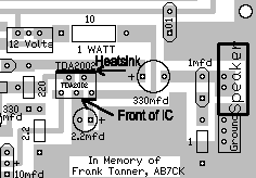 Some kits may have a LM383 or a house numbered part "9779", which are identical both in dimensions and electrical properties. |