455KHz IF Strip, AGC and S-Meter


To learn about the 455 IF, read the
Circuit Details - IF Strip
before building this section.

455kHz IF Strip
Approximate time to complete 0:22
Picture

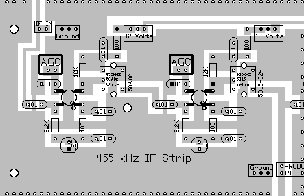
Insert all the components that have their values inside the footprint. They are the following:

____10 - .01 capacitors (Bag 3),

Solder

____4 - 100 ohm resistors (brown, black, brown) (Bag 3)

Resistors:

____2 - 12K (Bag 4), Above the right side of the MOSFETs.
____2 - 2.2k (Bag 4), Below the left side of the MOSFETs.

Solder

Other Parts:

____2 - MOSFETs (Bag 2), (Picture) static sensitive part, touch a ground wire before taking it out of the bag, notice the dot on MOSFET (may be difficult to see, hold at an angle to a light source and you can see the shadow of the dot), the dot is located to the left of the second line of the text on the MOSFET. A dot is placed outside the footprint so that you can double check your placement after it has been soldered to the PCB. The leads on each side of the part need to spread apart slightly to fit the footprint.

Solder

____2 - LED (Bag 3), Red colored, match the flat on the LED to the flat on the footprint. Located below the MOSFETs. The short lead is on the same side as the flat.
____1 - 50A02 455IF can, White core (Bag 5), Located on the right of the first MOSFET. After inserting into the board, touch the soldering iron to the IF can pins first, and make sure the pin is accepting solder before flowing solder onto the PCB. NOTE: The pins on the IF cans are very thick, and need proper heating to accept solder. Double check the soldering job very carefully.
____1 - 5015-024 455IF can, Yellow core (Bag 6), Located on the right of the second MOSFET. After inserting into the board, touch the soldering iron to the IF can pins first, and make sure the pin is accepting solder before flowing solder onto the PCB.

Solder

AGC and S-Meter

To learn about the AGC, read the
Circuit Details - AGC/Mute
before building this section.

To learn about the S-Meter Circuit, read the
Circuit Details - S-Meter
before building this section.

Approximate time to complete 0:42

Note: If you are using the Plastic S-Meter (the one listed on the order form), with the 200uA movement, for Mtr1 use a 22K resistor (check S-Meter package for resistor) instead of a 100K as shown on the PCB. That will lower the 100K resistors you will use to 3 instead of 4 as noted below.

The Mtr2 value will not change, a 100 ohm resistor will be used as noted on the PCB.

If you are using the 50uA S-Meter, use the values as shown on the PCB and follow the instructions below exactly.


Insert all the components that have their values inside the footprint. They are the following:

____7 - .01 capacitors (Bag 3)
____1 - small RF Choke (Bag 3), Footprint on PCB is a rectangle with square edges, "RF" inside the rectangle. Choke is about the size of a 1 watt resistor with rounded edges. Located next to the "12 Volts" and "Ground" boxes.
____1 - Large RF Choke (Bag 3), a large wire-wound RF Choke with black plastic ends. Located below the small RF choke. Large footprint labeled "Large RF". Picture

Solder

____3 - 100 ohm resistors (brown, black, brown) (Bag 3)

Solder

____4 - 100K resistors (brown, black, yellow) (Bag 3) Remember, if you are using the plastic S-Meter, the 100K resistor at Mtr1 will be 22K in place of the 100K.

Solder

Resistors:

____1 - 12K (Bag 4), Located above the right side of the MOSFET.
____3 - 2.2K (Bag 4), One below the left side of the MOSFET, second one to the right of the 1N270 diode, third one to the left of the Zero Adjust 10K trimmer.
____2 - 1M (Bag 4), Located to the right side of the 2.2K resistor.
____3 - 10K (Bag 4), one is located above the second 1M resistor, the second one is to the right of the cluster of 1N914 diodes, and the third one is below the "AGC" and "Mute" boxes.
____1 - 1K (Bag 3), Located to the left of the 2N3904 transistor.

Solder

Capacitors:

____1 - 10mfd Tantalum (Bag 4), 3 pin (Bag 4), The center pin is positive, two outer ones are ground, this part is used in automatic insertion PCB work so that it never gets put in wrong, located to the right of the 2N3904 transistor.
____1 - 330mfd Electrolytic (Bag 4), Note: - (Minus) is marked on the part, and the + (Positive) is marked on the board. Located at the upper right corner of the section.

Solder

Other Parts:

____1 - LED (Bag 3), Red colored, match the flat on the LED to the flat on the footprint. Located below the MOSFET. The short lead is on the same side as the flat.
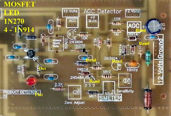
____4 - 1N914 diodes (Bag 4), Black band, very small size. Be sure to match the band on the diode to the band on the footprint. Three are in a cluster below the second AGC square on the right side. The other one is above the FET (2N5486).
Bend the leads about 1/8" away from the body of the diode for easy insertion into the PCB.
____1 - 1N270 diode (Bag 6), Black band, larger size than the 1N914's. Be sure to match the band on the diode to the band on the footprint. Located to the right of the 455KHz IF can.
____1 - MOSFET (Bag 2), (Picture) static sensitive part, touch a ground wire before taking it out of the bag, notice the dot on MOSFET (may be difficult to see, hold at an angle to a light source and you can see the shadow of the dot), the dot is located to the left of the second line of the text on the MOSFET. A dot is placed outside the footprint so that you can double check your placement after it has been soldered to the PCB. The leads on each side of the part need to spread apart slightly to fit the footprint.

Solder

____1 - 50A02 455IF can, White core (Bag 5), Located to the left of the MOSFET. After inserting into the board, touch the soldering iron to the IF can pins first, and make sure the pin is accepting solder before flowing solder onto the PCB.
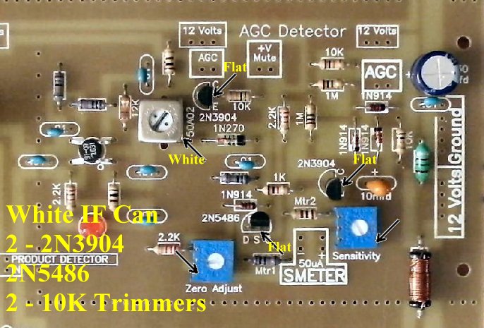
____2 - 2N3904 transistors (Bag 4), Note flat on part and match to the flat on the footprint.
____2 - 10K Trim pots (Bag 5), Blue color, Located on either side of the S-Meter box. Colored blue, Marked "10K" on the side. Set both trim pots to the middle of their range.
____1 - 2N5486 (Bag 4), Spread the end pins slightly so they fit through the holes. Do not force all the way down onto the PCB and stress the pins. Note flat side of part and match to the flat side of the footprint.

Solder


____Cut one 3" length of hookup wire and connect the AGC Squares (BOLD lined squares) at the first and second amplifier in the IF strip. This can be done underneath the board to provide a cleaner appearance above the board. Picture
____Cut one 6" length of hookup wire and connect the AGC Squares (BOLD line squares) between the second MOSFET amplifier in the IF strip and the AGC Square that is located on the far right of the IF strip, just to the left of the 330 electrolytic cap, in the "AGC Detector" section. This can be done underneath the board to provide a cleaner appearance above the board.
____Cut one 2" length of hookup wire and connect the last AGC square with the AGC square above the 2N3904 transistor. The transistor controls the "Mute" function of the receiver. This wire can be left off if you never intend to use the receiver with a transmitter.

Solder

Double Checking Your Work

____Check the dots on the MOSFETs.
____Check the flat on the LED and make sure it fits the flat on the footprint.
____Check the flats on the 2N5486 and the 2N3904.
____Check the black bands on the three 1N914 diodes.
____Check the black band on the 1N270 diode.
____Place the PCB in front of a bright light. If you see light shining through any of the soldering holes, you missed a solder connection.

Superluminescent Receiver - Construction - Board 2, Section 3

Send E-Mail || Amateur Radio Receivers || Back to Instructions for the SuperLuminescent Receiver


Last Update: 10/25/2015
Web Author: David White, WN5Y Free Website Translator