
To learn about the Second Mixer, read the
Circuit Details - Second Mixer
before building this section.
To learn about the Crystal Oscillator, read the
Circuit Details - Crystal Oscillator/Amplifier
before building this section.

|
____Mount spacers on each side of the board on the four corners to provide support for insertion of parts and easy soldering. Picture |
|
Insert all the components that have their values inside the footprint. They are the following: ____15 - .01 capacitors (Bag 3) |

|
Solder |

|
Solder |

|
Solder Resistors:____2 - 1K (Bag 3), One is located on the left side of the 30/17 LED, and one is located on the right side of the 30/17 LED |

|
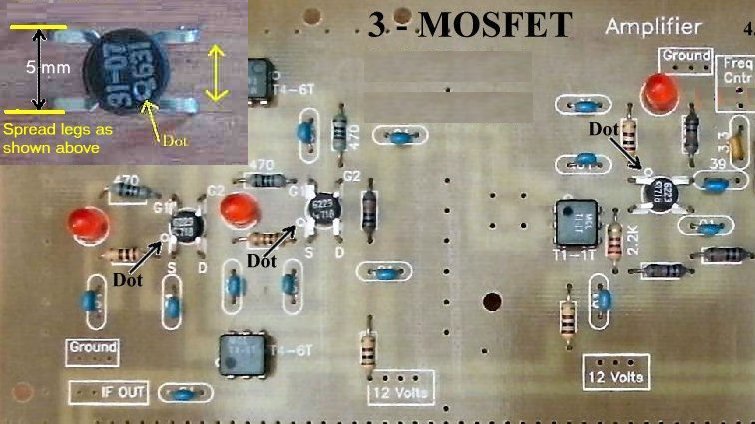
Solder Capacitors (Going left to right on the board):____2 - 100pf NPO (Bag 3), Located at the left side and above the FET (2N5486). Orange color, short leads flared out, labeled "101". |

|
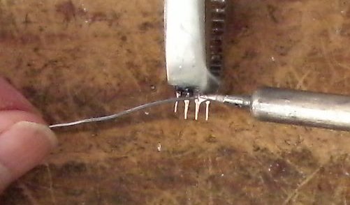
Solder Other Parts:____5 - LEDs (Bag 3), Red colored, match the flat on the LED to the flat on the footprint. The short lead is on the same side as the flat. Note: Tin all the leads on the transformers - T4-6T and T1-1T - as the pads they solder to are small. This will make a solid solder joint. Wipe the excess solder to the top of the pin so it will fit in the holes. |
|
Solder |

|
Solder Crystals____1 - 4.000MHz crystal (Bag 4), The markings are "4000 KSS 2FT". |

|
Solder |
|
|
|
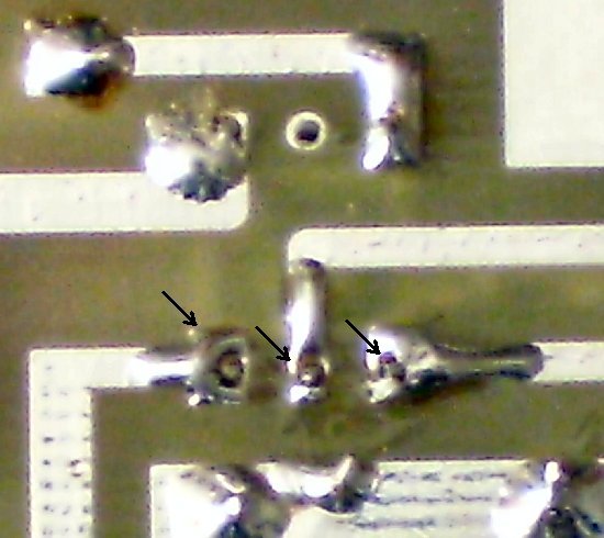
____Check the dot on the MOSFETs and the Minicircuits transformers. |
|
|
Send E-Mail || Amateur Radio Receivers || Back to Instructions for the SuperLuminescent Receiver

