

|
The crystal layout is universal. Use the two pads inside the oval that fit your crystals the best.
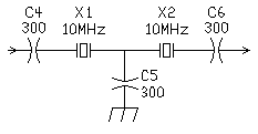
The crystal filter bandwidth can be changed with capacitors C4, C5, and C6. Higher values of C4, C5, and C6 give a tighter bandwidth, while lower values of C4, C5, and C6 will give a wider bandwidth. Use the same value for C4, C5, and C6. Recommended values for CW are 200 to 300pf and for SSB, 39 to 100pf. The author's experience has been that lower frequency crystals work better for CW work. Some surplus crystals in the 3 to 5 MHz range have resulted in bandwidths of 300 to 700 Hz using 300pf caps and three pole filters. There is plenty of room in the middle of the board to experiment with different crystal filters. Higher frequency crystals (10-20 MHz) work great for SSB reception and usually result in bandwidths of 2-3 kHz. After selecting a set of crystals, a VFO frequency is either added to or subtracted from the crystal frequency to equal the frequency of the band of operation. For example, a 40 meter CW receiver with 4 MHz crystals, use a 3 MHz VFO (4 MHz crystals + 3 MHz VFO = 7 MHz). For a 40 meter SSB receiver with 10 MHz crystals, use a 3 MHz VFO (10 MHz crystals - 3 MHz VFO = 7 MHz). See the chart with the VFO winding data for other examples. When the VFO frequency is subtracted from the crystal frequency, remember that the VFO will tune backwards (tuning cap open for alignment at low band edge).
|


Return to: Beginner and Experimenter's Receiver Kit
|| Send E-Mail
