

|
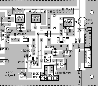
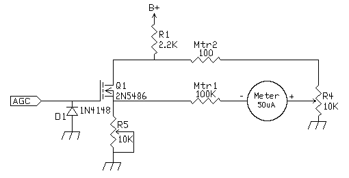
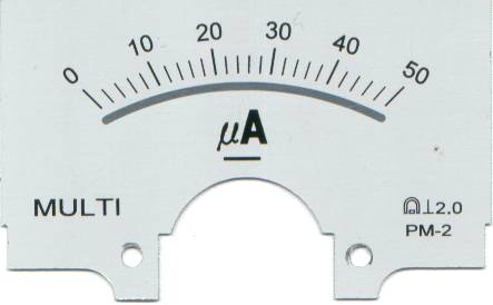
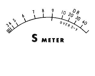
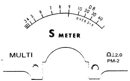
The AGC voltage goes directly to the gate of the 2N5486. Normal voltage with no AGC applied (full gain) is 6 volts, so the FET is turned on. In order to show zero reading on the S-Meter, the voltage from the two legs of the circuit should be equal. This prevents current from flowing through the S-Meter. One leg of the circuit is through R1, a 2.2K resistor, through the FET to the source connection, and R5, the 10K variable resistor to ground. The other leg of the circuit is through Mtr2, a 100 ohm resistor, R4, a 10K variable resistor, the S-Meter, and Mtr2, a 100K resistor. Both legs terminate at the source of the FET, and the voltage at that point is controlled by the gate voltage of the FET and the 10K variable resistor. R1 sets the maximum amount of current that flows through the circuit. For meters over 500uA, R1 value should be lowered to have more current available for higher value meters. The diode on the gate of the 2N5486 was needed to prevent the gate from being blown by a spike. This protects the 2N5486 as well as G2 on the MOSFETs. Best sensitivity is achieved with the pots at the high end of their range, especially R5. Mtr1 can be adjusted to get R5 (zero adjust) to be at the high end of its range. With higher value meters, you may not need any resistance at Mtr1. If R5 (zero adjust) is set toward the ground end of its range, it can turn off the LEDs on the IF strip. As the AGC is turned on, lowering the AGC voltage, the FET begins to turn off. This lowers the voltage at the source of the FET, and current begins to flow through the S-Meter through R5, a 10K variable resistor, connected to the source of the FET. This circuit is set up to use a 50uA meter with the values marked on the PCB for Mtr1 and Mtr2. Using Junk Box Meters for the S-MeterMeters up to 500uA can be set up to work by changing the Mtr1 and Mtr2 values. Mtr1 and Mtr2, plus the adjustment on R4, determine the maximum amount of current that can flow through the meter. For regular meters, Mtr2 is left at 100 ohms, and the Mtr1 value is lowered so that enough current can flow through the meter to make it read full scale, with R4 set at mid range. For center reading meters, that need to have an opposite current flow through it to make it read zero, the normal Mtr1 value is divided between Mtr1 and Mtr2. Some experimenting is necessary, but the following values will get you close. 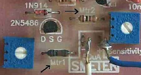 Other values will be posted as they are tested. Fine Tuning S-Meter ResponseThe response of the S-Meter is dependent on the FET type. The MESFETs, with their sharp turn-on, didn't work well, it was either full scale or no response. The 2N5486 worked well, but other devices could do as good a job or better. A high impedance gate is necessary to keep the timing of the AGC circuit. Fine tuning this circuit would involve studying the turn-on characteristics of a device, then matching the AGC voltage to that of the device for a linear turn on/off curve. Customizing the Meter FaceThe meter face of the plastic meter is about what you want for an S-Meter. But the 50uA meter has a 0-50 uA reading which does not easily translate to the logaritmic scale of an S-meter. For those who want a custom face showing S-Meter readings, check out "Custom Meter Faces: A Pictorial Instruction". With a scanner and a picture program, like Paint Shop Pro, a custom meter face is very easy to produce. The following are some pictures that might help in making a new S-Meter face for the 50uA meter. Just right click the image, then left click on "Save image As". Then open in your picture program and use the instuctions noted in the above paragraph. |
|
The last picture above was my attempt at combining the two above pics and making a new face. Download the picture, increase the resolution to 300dpi (if it is a feature of your picture software), and print at a width of 2.19" and a height of 1.37". In Paint Shop Pro, go to Page Setup, Check "Maintain Aspect Ratio", uncheck "Use Full Page", set width at 2.2", click on height box to auto set that value, then print. Put the old meter face over the print and cut out. |
|
A small LED [T1(3mm)], can be used to backlight the plastic S-Meter with a little effort. A T1 Bright Blue makes a very nice display but can be too bright when trying to take pictures of the receiver in dim light. A T1 regular Red works very well and does not overwhelm a picture taken in dim light. The basic procedure is to drill either a 7/64" hole (.109") or a 1/8" hole (.125") into the side of the S-Meter and secure the LED into the hole. A T1 LED is .118" in diameter which is right in between a 7/64" and 1/8" drill bit. Drilling with a 7/64" bit makes for a very tight fit. Drilling with a 1/8" bit leaves a loose fit for the LED. A bit of glue or silicon will fix the loose fit. Connect the LED to a 12 Volt connection with a 1K resistor. Ground the shorter lead of the LED (also indicated by the flat side of the LED). 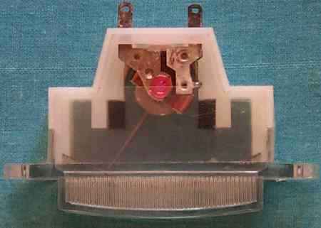 Shown above is a picture of the S-Meter. The LED is easily mounted on either side. Check how you are going to mount the S-Meter and decide which side would be best to install the LED.
Picture shows one place where a hole can be made for the LED. This location is best for the Super Bright LEDs (Blue, Green, Blue/Green, White). The LED shines right on a plastic piece which helps difuse the light. For the less intense regular Red LED, drill forward just ahead of the plastic piece so the light can spread all across behind the faceplate. The black arrow shows the location to drill. Be sure to miss the edge of the faceplate. 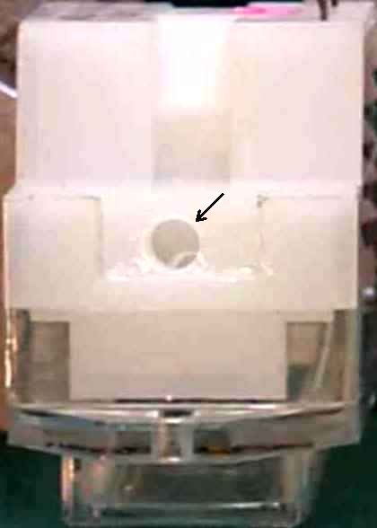 Picture shows the hole from a side view. The hole is 1/8" diameter which is a slightly loose fit for the LED. RPM of the drill should be very slow. The hole can be drilled by hand with a new, sharp bit. The plastic is very soft. Be very careful with an electric drill when breaking through - use very light pressure and slow RPM. The case may crack if you are not very careful. 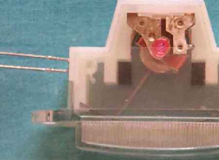 A Super Bright LED mounted in the S-Meter. 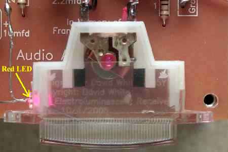 The suggested location for a regular Red LED closer to the front of the S-Meter. 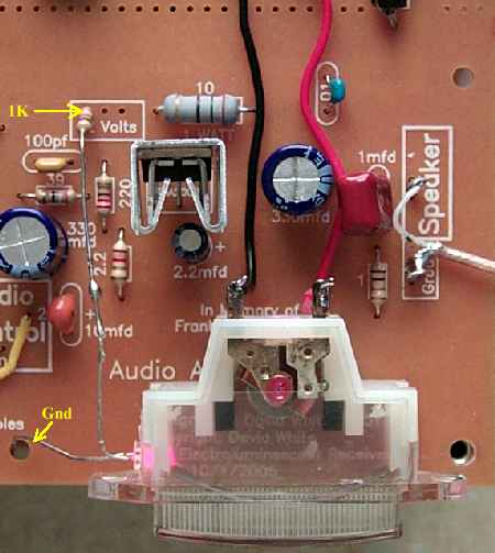 Picture shows the 1K resistor, 12 Volt and ground connections. The S-Meter can also be mounted underneath the board with no extra trouble. |

