


|
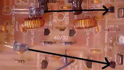
Notice that the IR LED is not installed next to the Filter Tune pot and the 820pf mica caps installed laying down toward each other for minimum interference with the IRED path. The Photodiodes are bent toward the IREDs for better illumination from the IREDs. These paths are sensitive to low receiver voltage. |


|
Shows how the 20/17 Meter IRED is mounted on the Bandpass Filter Section. The IR LED next to the 20 meter bandpass relay is not installed. |



|
Notice the IR LED above the bandpass pot is not installed in the SWL version of the receiver. |

|
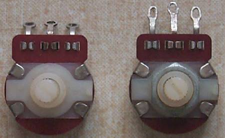
The pot on the left is the untouched pot as it comes out of Bag 6. First, the solder lugs are bent straight out from the pot. Second, the end solder lugs are pushed inward slightly. Third, the solder lugs are crimped just enough to fit through the holes. |

|
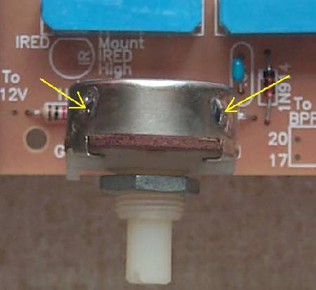
Clean the outside of the pot with a sharp razor, fine grit sandpaper, or a sharp knife and then tin the spots as shown above in the picture. These spots will be used to solder ground wires and provide mechanical stability for the pot. |

|
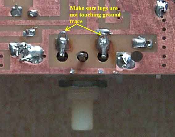
Insert the pot into the PCB board, bend the two outside lugs backwards so they are resting on the solder joints of the resistors. When soldering the lugs, adjust the pot so it is in line with the edge of the PCB board and facing straight outward. Reheating the solder and making slight adjustments will get it perfect with no problem. The lugs extend over the ground plane trace just below. If desired, the lugs can be trimmmed so there will be no chance they can short to the ground trace. Or be careful that solder does not run from the solder lugs onto the ground trace. A VOM or DVM can be used to double check that the lugs are not shorted to ground. |

|
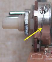
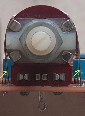
The arrows in the pictures above show the wires that are soldered to the pot. Since the case is not mounted in a metal case and naturally grounded, a ground wire is soldered to the case so that it does not pick up stray RF from the PCB or your hand. The wires also provide mechanical support. |


|
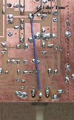
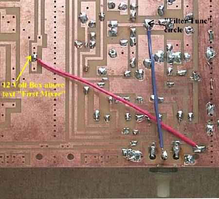
Be sure to place the wire in one of the group of three holes. The one below the group of three is used for an RF Choke on top of the board. |
