

|
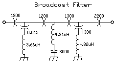
The TV & FM Filter used in this receiver is a 30 MHz low pass design based on the article in the September/October 2000 issue of QEX called "Narrow Band-Pass Filters for HF", by William Sabin. These filters are implemented using fewer parts than other double-tuned NBPFs and they work very well.  The broadcast filter is from most of the recent Amateur Radio Handbooks ("A BC-Band Energy-Rejection Filter", Filters and Projects, The ARRL Handbook, 1999, pp 16.36). 4.5 MHz High Pass FilterNote: The parts for this filter are not included in the kit.
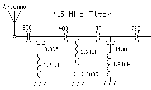
An upgrade to just building a broadcast filter is to build a 4.5 MHz high pass filter. A 4.5 MHz filter keeps interference out of the IF frequencies and the broadcast bands. The PCB boards currently shipping have the values for this 4.5 MHz filter. The Handbook article ("A BC-Band Energy-Rejection Filter", Filters and Projects, The ARRL Handbook, 1999, pp 16.36) illustrates how the filter can be scaled for other frequencies. Multiplying the frequencies by a factor of 3 yields a 4.5 MHz filter. This means dividing all the values of the filter by 3. The following table gives the values. Getting the calculated values close, the filter started rolling off at 6.5MHz and was >60dB down at 4.5MHz. |

| 4.5 MHz High Pass | Cap Values | T50-2 Turns | T50-6 Turns | Wire Length |
| 600pf | 2 - 300pf or, 1 - 270pf & 1 - 330pf |
- | - | with 1" leads |
| .005mfd | 5100pf or 5000pf |
- | - | - |
| 400pf | 2 - 200pf |
- | - | - |
| 1.22uH | - |
16 | 18 | 16T - 12", 18T - 14" |
| 1000pf | 1000pf | - | - | - |
| 1.64uH | - | 18 | 20 | 18T - 14", 20T - 15" |
| 430pf | 430pf or 438pf | - | - | - |
| 1.61uH | - | 18 | 20 | 18T - 14", 20T - 15" |
| 1430pf | 430(438)pf & 1000pf | - | - | - |
| 730pf | 430(438)pf & 300pf | - | - | - |
|
Most of the caps can be ordered from Kits and Parts and the 1000pf and 5000pf/5100pf can be found on Ebay.
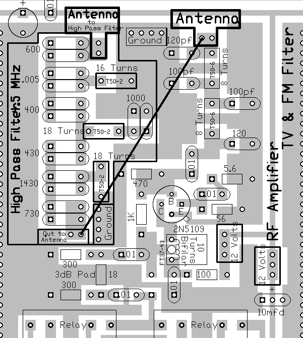
Below is the layout of the filter showing where all the values for the 4.5 MHz Filter are placed. There are two footprints for each value which gives room to make up the capacitance needed with two capacitors in parallel. Some of those values may be hard to find. Being able to parallel a couple of capacitors makes it easier to get values close to the ones in the filter. Notice that a wire is run from the normal Antenna Input to the output of the filter and the antenna connection has been changed to the Antenna Input at the top of the Broadcast Filter. |

|
|
|
|
Send E-Mail || Amateur Radio Receivers || Blue Lightning Transceiver

