

To learn about the Bandpass Filters, read the
Circuit Details - Varicap Tuned Bandpass Filters
before building this section.


|
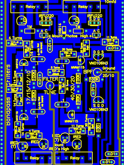
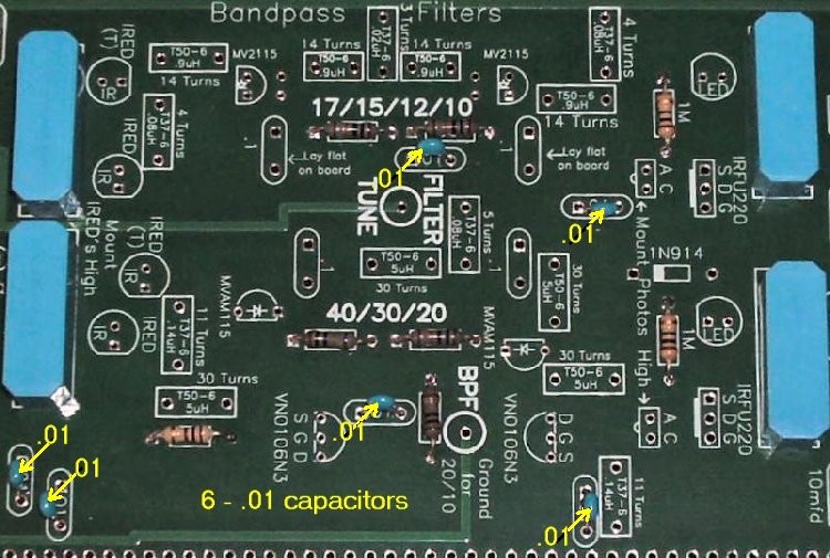
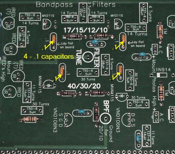
____5 - 100K resistors (Bag 3) (brown, black, yellow)   ____6 - .01 capacitors (Bag 3)   ____4 - .1 caps (Bag 4)   ____1 - 1N914 diodes (Bag 4), Black band, be sure to match the band on the diode to the band on the footprint, one on each end of the filters near the middle of the board and a third in the lower left hand corner.   ____2 - MVAM115 (Bag 5), Be sure to match the flat of the component to the flat on the footprint. Spread the leads apart to fit the footprint. Marked MVAM, 115 ____2 - LEDs (Bag 3), Red color, at the left side of the relays on the right. Match flat of the LED to the footprint. The short lead is on the same side as the flat. Note: If you ordered the Super Bright LEDs, they can replace these LEDs. Use different colors so band identification will be easy. See Modifying the LEDs.   ____2 - IREDs (Bag 4), Smoky colored, on a cardboard strip, do not cut the leads off the strip, tear the IREDs off the strip and clean the bottom of the leads. Mount as high as possible, then aim to the appropriate photo receiver. They are located to the right of the output relays on the left.   ____2 - 1N914 diodes, Match black band to white band on footprint ____1 - SPDT slide switch for Band Switch footprint. There are two hole patterns. Mount the switch in the holes that fit the switch in Bag 5.   Install 100K Potentiometer____1 - 100K Panel Mount Potentiometer (Bag 6), The three holes labeled "Filter Tune" should accept the pins of the potentiometer supplied with the kit.   ____2 - 1K resistors (Bag 3), One on either side of the 100K pot.  |


TV & FM Filter and RF AmplifierTo learn about the TV and FM Filters, read the Circuit Details - TV & FM, Broadcast Filters. To learn about the RF Amplifier, read the Circuit Details - High Level RF Amplifier.  Approximate time to complete 0:35 Approximate time to complete 0:35 The 4.5 MHz High Pass Filter is optional. The parts for the High Pass Filter are not included in the kit. If you live in a large metropolitan area where several high power AM stations or nearby amateur radio stations are present, you might consider installing the parts. Check out TV & FM, Broadcast Filters for information. |


 ____1 - 2N5109 Transistor and Heatsink (Bag 6), Put the heat sink on the transistor first before soldering to the PCB. 
|


|
____Place the PCB in front of a bright light. If you see light shining through any of the soldering holes, you missed a solder connection. |
Send E-Mail || Amateur Radio Receivers || Back to Instructions for the SuperLuminescent Receiver

