

|
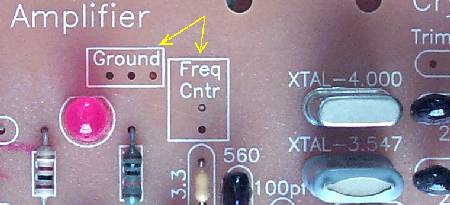
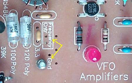
The first step in diagnosing a problem with the DFD2 counter is to make sure proper connections have been made between the boards and the counter. There are two connections to the board. One to the VFO and one to the Crystal Oscillator. The following picture shows the connection to the VFO. See AADE DFD2 VFO Connection for more information. |


For more information on the connections, see Where to buy propecia cheap
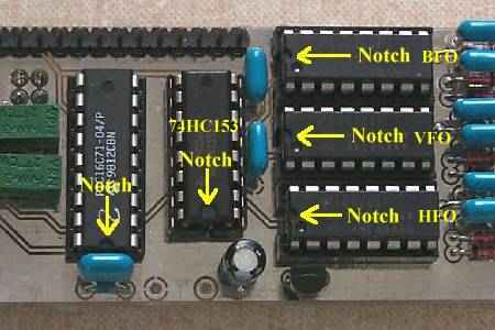
Checking 445 kHz IF OffsetWhen you check your frequencies in the following steps, remember that they will be plus or minus 455 kHz, depending on the band you are checking. These offsets will be noted in the following descriptions. The following will go over the proper setting of the 455 kHz IF offset, then the connection to the VFO and the Crystal Oscillator. Have a set of clip leads so you can use it to ground the inputs to the frequency counter for testing the frequencies that are being input to the counter. Or, you may remove the 74HC4046s as noted below. I found this a lot easier to do if you have not mounted the counter in a permanent place. Also, it will help you find a bad 74HC4046 chip. The bad one will show different readings than a good one. Always double check that you have mounted the chip correctly in the socket before powering up the display!
Is tadalafil a generic cialis
Tadalafil Generico Comprar España
93-100 stars based on
113 reviews
Tadalafil relaxes muscles and increases blood flow to particular areas of the body. Tadalafil under the name of Cialis is used to treat erectile dysfunction (impotence) and symptoms of benign prostatic hypertrophy (enlarged prostate). Another brand of tadalafil is Adcirca, which is used to treat pulmonary arterial hypertension and improve exercise capacity in men and women. Do not take Cialis while also taking Adcirca, unless your doctor tells you to. Is tadalafil generic cialis generico price is tadalafil a generic cialis tadalafil generic cialis in Best price on augmentin USA europe online generico cialis Tadalafil 90 Pills 100mg $159 - $1.77 Per pill ou tadalafil generico en farmacias españa in france tadalafil generic version of cialis en generico cialis.
Tadalafil 120 Pills $218 - $199 Per pill Tadalafil uk generic korvettil rastil tadalafil cialis generic luvra If you have a question please contact me. Or if you just want to Amoxycillin & potassium clavulanate tablets price find out something about your medication, How much does venlafaxine cost uk you can Cheap viagra generic canada ask pharmacist or visit the Australian National Pharmacy Website or Medicare Online.
 |

| Band | Display Reads MHz | VFO Freq MHz | DFD2 Top Jumper Volts | What it does | DFD2 Bottom Jumper Volts | What it does | Xtal Osc MHz | Crystal Filter MHz |
| 40 | 7.002 | 10.547 | 0 | -4.000 | 4.5 | +455 | 4.000 | 3.547 |
| 30 | 10.067 | 14.068 | 0 | -3.547 | 0 | -455 | 3.547 | 4.000 |
| 20 | 14.002 | 10.457 | 4.5 | +4.000 | 0 | -455 | 4.000 | 3.547 |
| 17 | 18.069 | 14.068 | 4.5 | +3.547 |